
I am currently working on a robotics platform and educational system I have code named “RoboDojo” for the time being. My intention is to create an open source robot that is easy to manufacture, with as low of a cost to the end user as possible, and robust enough to find value in educational environments from elementary school to the college level.
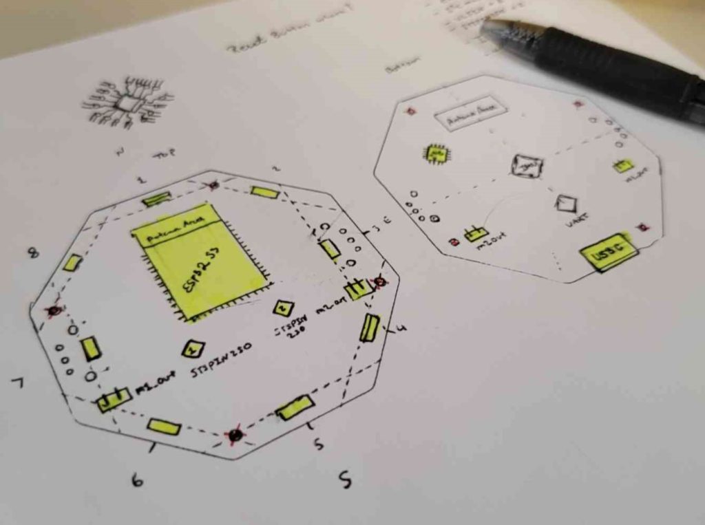
I really wanted to build the time of flight sensors into this board, and I had the idea of making a hat for the board with small mirrors at 45 deg angles above each sensor. This is far from a good idea, especially when I am trying to make the minimum viable product for an educational market. The ToF sensor array would add far to much cost, complexity, and uses up all my I2C mux ports. I want people to add sensors they want to it so I will create a sensor project for the Dojo. There are some elements of this layout I like, such as the I2C mux package, but it is far more expensive than the alternative package so I will change that for the next revision. Due to realizing the T.o.F sensors are going to be a hassle, and I want to change the board form factor. I will not build this version and focus on getting V4 out to fabrication and the B.O.M created and ordered.

https://github.com/Amoskeag/RoboDojo/releases/tag/V4.0
This iteration lacks a feature I thought was critical to making a better robotics kit for students, an IMU! I will need to use the I2C bus to get data from an external IMU for testing, but one of the important lessons for keeping students engaged (from my experience) is how do I make a robot move in a straight line. This is a very basic lesson in control systems, but I think when students see the results and are navigating mazes more accurately that leads to an empowered mindset. V4.1 will make sure an IMU is chosen and mounted to the PCB.
Another thing I was thinking about was the original Official Arduino Robot kit:
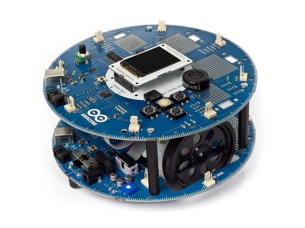
“The robot has two processors, one on each of its two boards. The Motor Board controls the motors, and the Control Board reads sensors and decides how to operate.” – Arduino Retired Products Site.
I really love the compass marks around the PCB edge. I should see what I can learn from this previous design in educational robots and improve my design based on what i find.
Oh hey, this exists: https://www.arduino.cc/education/arduino-alvik/
Okay so what am I doing? Well, I’m teaching myself robotics from the ground up and trying to take students through that process as well. I want the system to be useful for K-12, but I also want to use this to get more people learning about hardware design and building custom PCB’s as well. Alvik feels like its really trying to engage with the K-12 market exclusively, whereas I want my project to speak to the college student, and the hobbyist who wants to try new things. I should learn what’s working with each of these designs, and make changes based on engineering design notes, and what people in my community have to say about the project. Rome wasn’t built in a day, and neither is Homegrown Robotics.
My next steps:
Get the boards in from JLCPCB.
- Get the boards in from JLCPCB
- Assemble a working prototype
- Make a short video to document everything that has happened to this point.
Next up: Getting the first board running (Posting in March!)